01 Why build an editable model from 3DGS?
3DGS preserves the colour, light and arrangement of objects with an appearance that stays close to the captured place.
That visual fidelity is valuable for reviewing a location and finding camera angles.
Tasks such as moving one wall, changing the stage, or hiding a railing require conventional geometry.
This project therefore keeps the 3DGS as the record of the existing space while rebuilding the hall as editable meshes.
02 Use 3DGS and captured images for different purposes
The source material includes the complete hall 3DGS and the PortalCam capture data.
I extract the left and right camera images so that details obscured in the 3DGS can be checked from other angles.
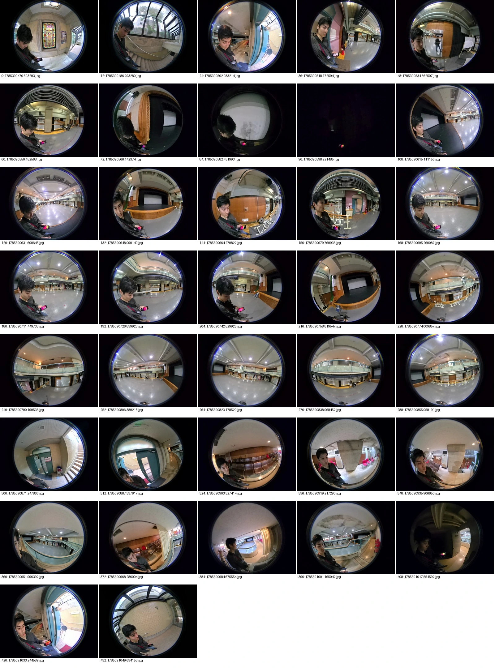
Use 3DGS to understand the complete spatial relationship and appearance. Use the captured images to inspect component shape and material.
Separating these roles helps prevent scan gaps and floating noise from becoming part of the building.
The extraction process is covered in Extracting 4K Source Images from PortalCam's Raw Data (.xbin).
03 Overlay 3DGS in Blender and compare matched cameras
First, import the 3DGS into Blender and place the model in the same coordinate system.
Then lock cameras for the stage, rear, sides, ceiling and upper gallery.
Rendering the model and 3DGS from the same position and field of view makes width and height differences easier to identify.
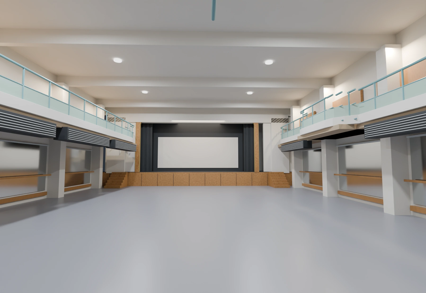
Matching the camera does not make 3DGS and CG lighting identical.
I separate brightness and colour differences from geometry, focusing on beam outlines, floor contact and the way parts overlap.
04 Build with Codex and redirect the work with images
Codex runs Blender scripts to add walls and beams, render the result and compare it with the original 3DGS.
I inspect the comparison images and direct which area to address next and how its geometry should be constructed.
Attempting the entire hall in one pass spreads incorrect assumptions across the scene.
I divide the work into the ceiling, upper gallery, stage and wall-side equipment, and review every area from more than one angle.
05 Correct the construction of the geometry
An earlier version formed curved elements from chains of short cylinders.
The joints remained visible and did not read as architectural elements.
I redirected these parts into continuous geometry and checked their transitions at close range.
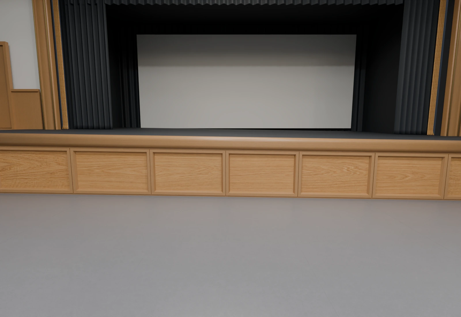
The stage-front panels also began with borders that were too wide and centres that were too deeply recessed.
Matched 3DGS views guided a slimmer border and shallower recess.
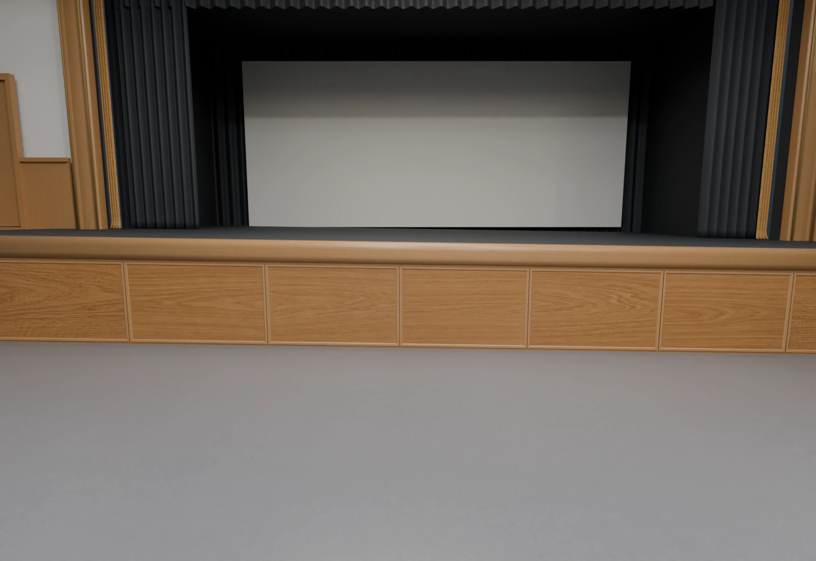
06 Build the wood and other materials
Repeating one wood image on every panel creates an obvious CG pattern.
I used image generation to create different grain regions for the stage front and assigned a different region to each panel.
The generated wood is not a photographic texture of the actual material.
It is a generic approximation of colour and grain direction, not a claim about the exact species or pattern.
The border profile and finish brightness are adjusted together with the grain.
07 Compare six locations with the original 3DGS
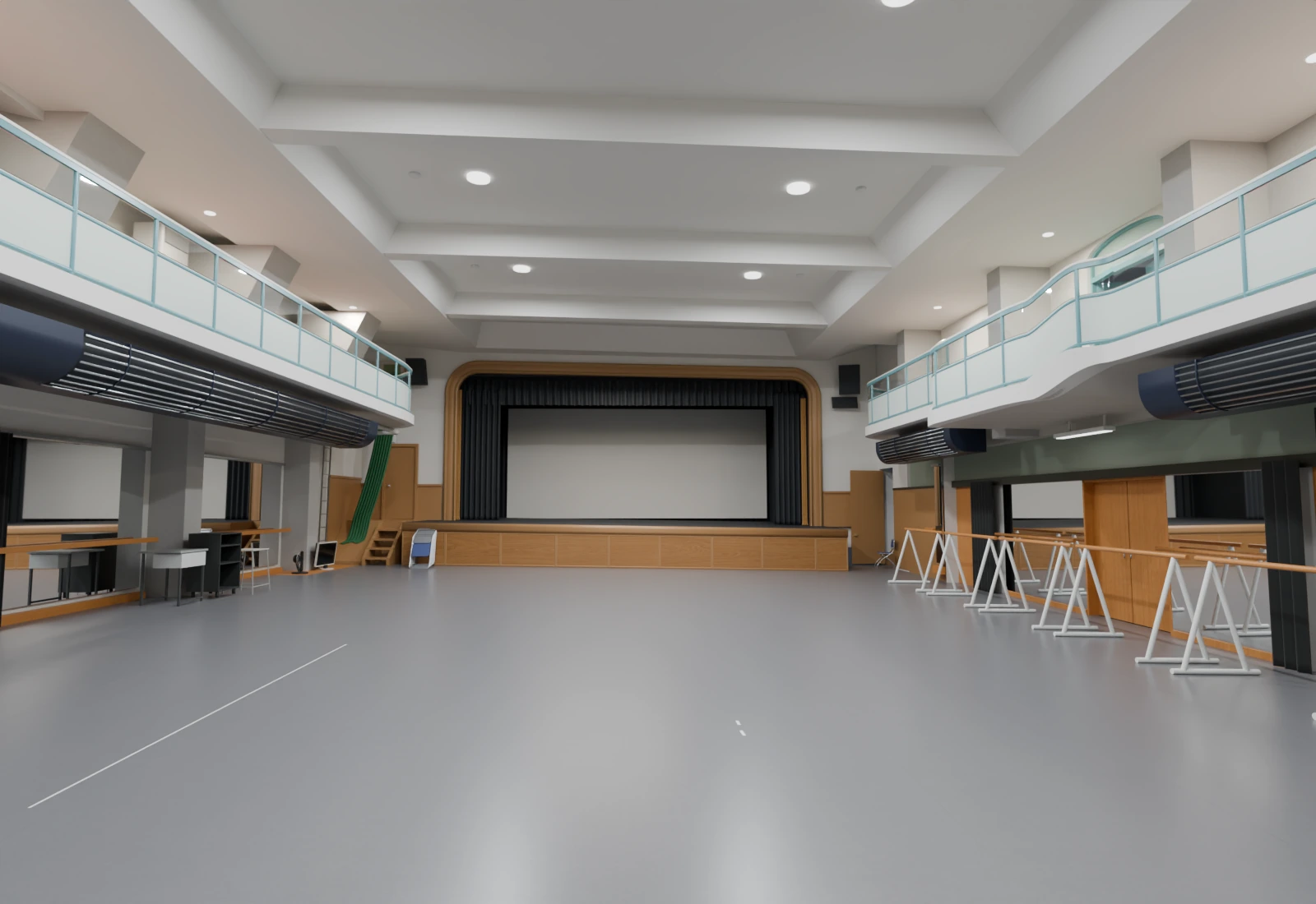
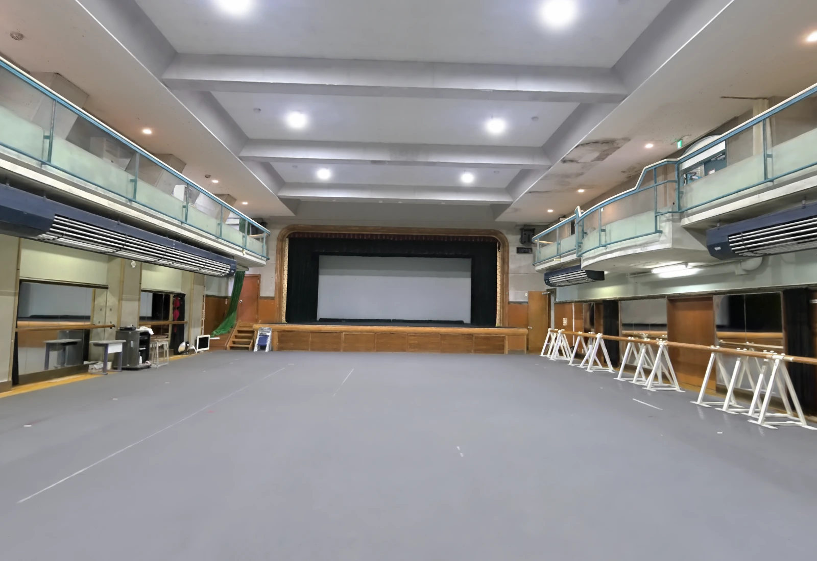
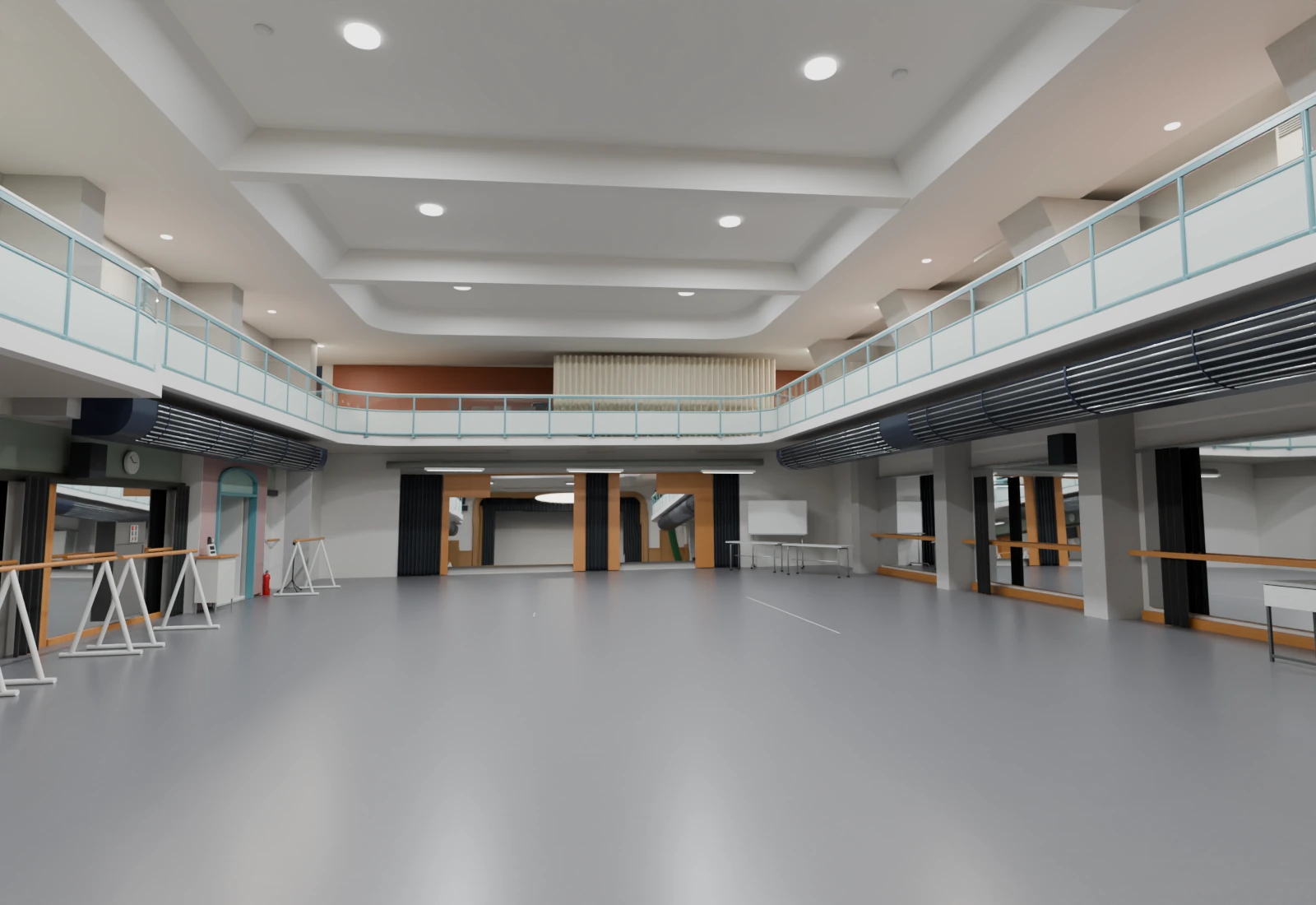
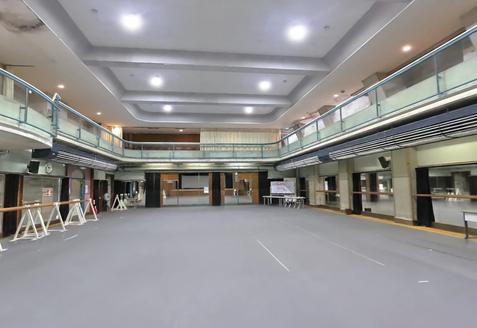
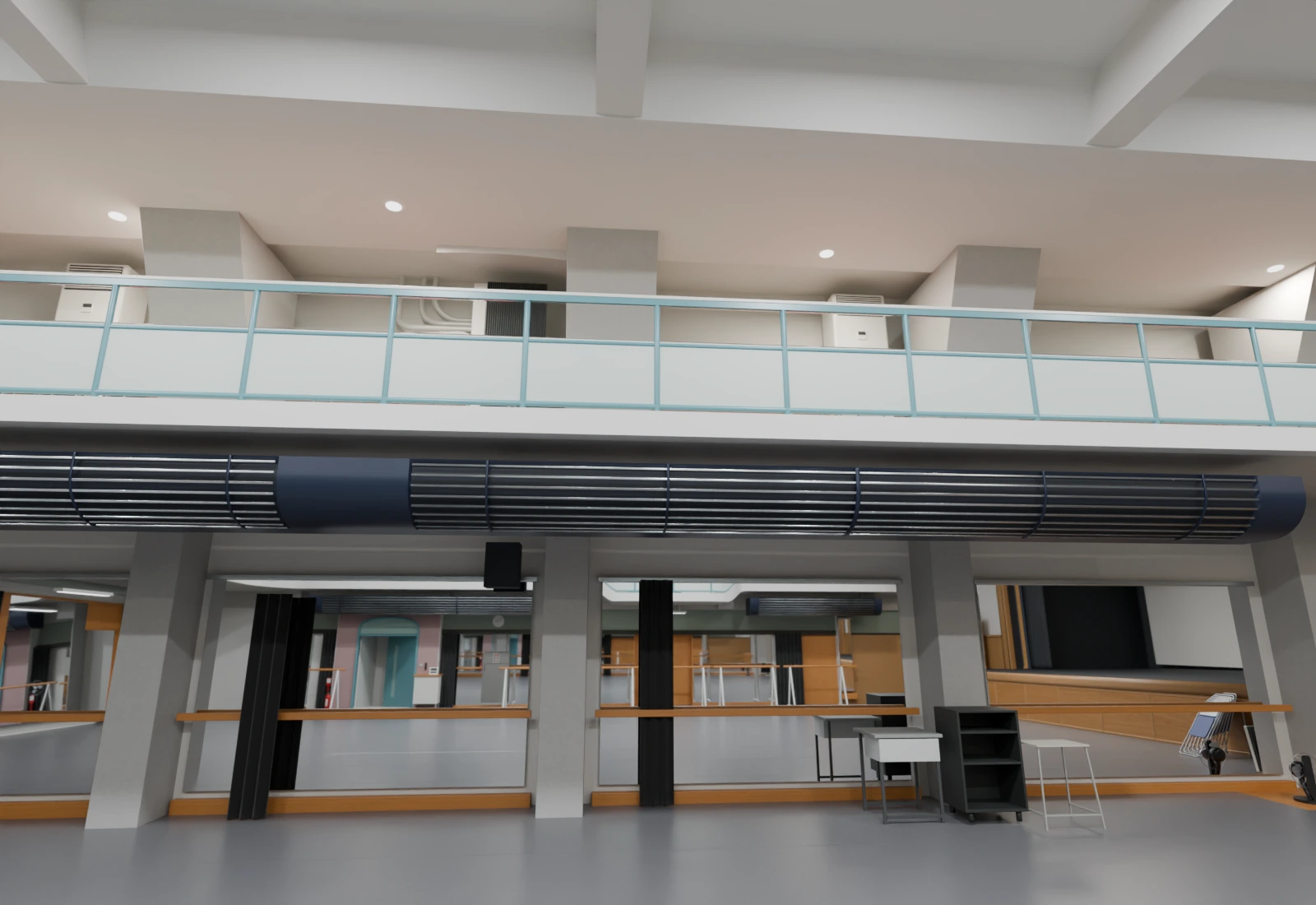
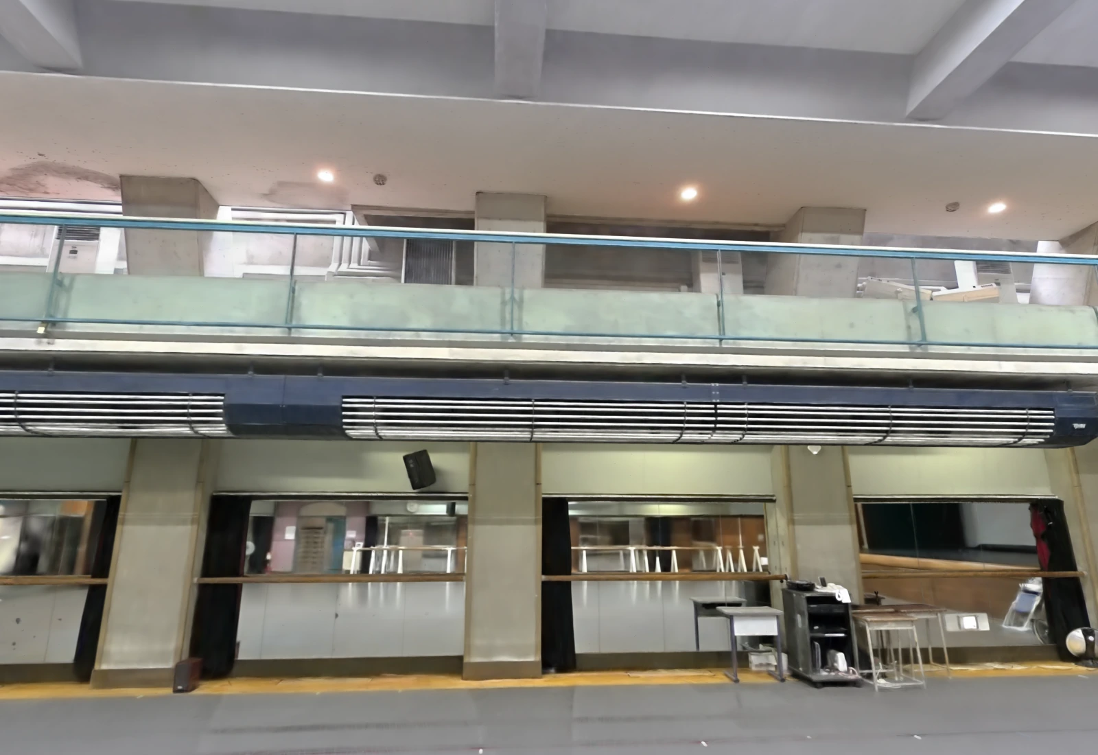
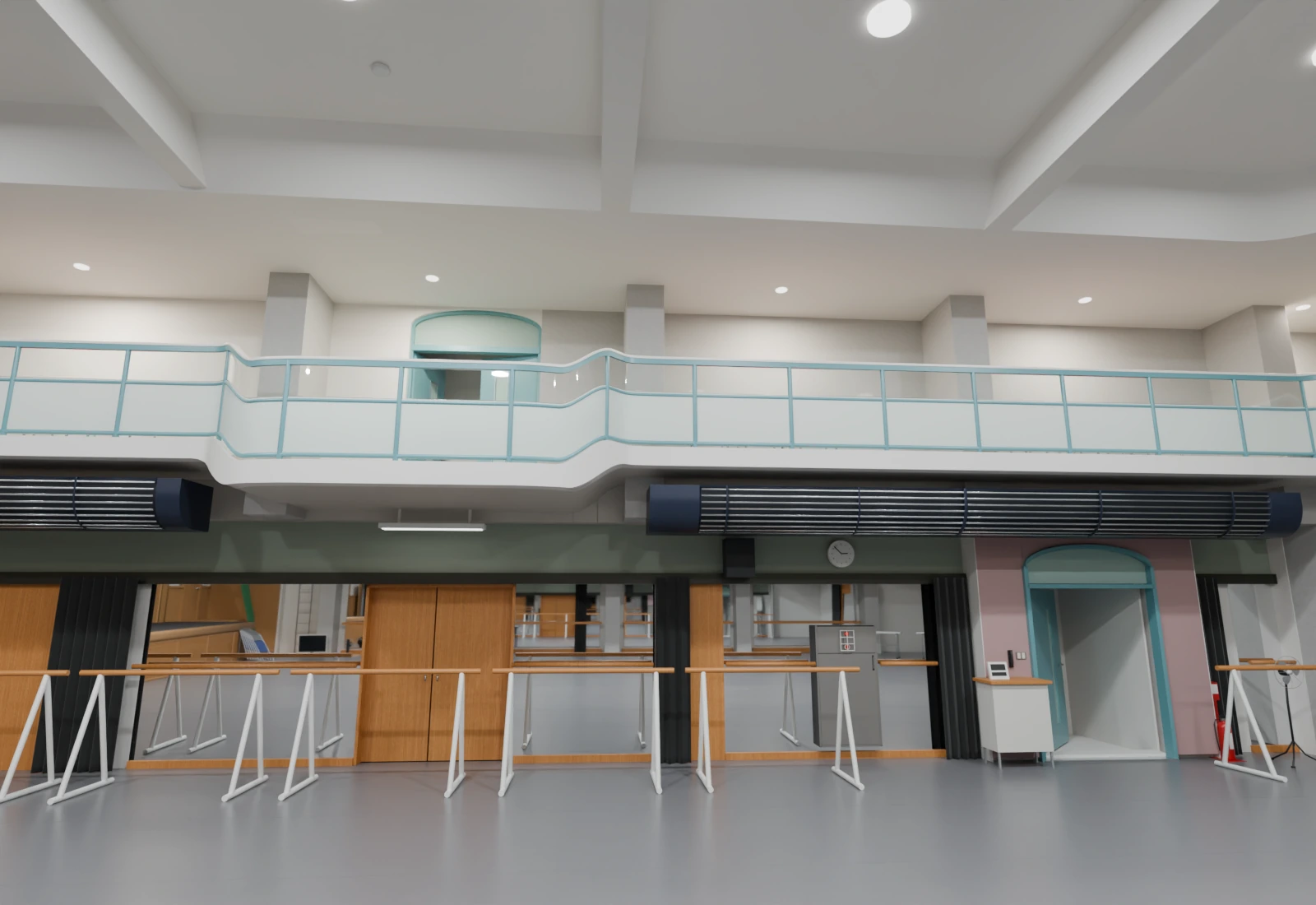
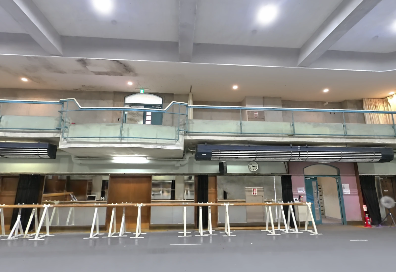
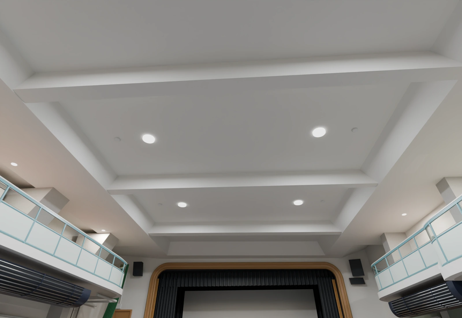
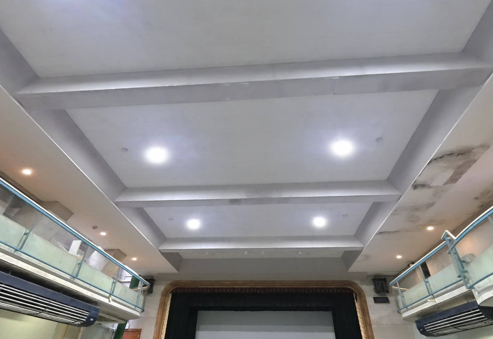
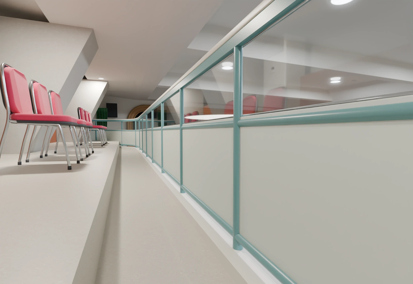
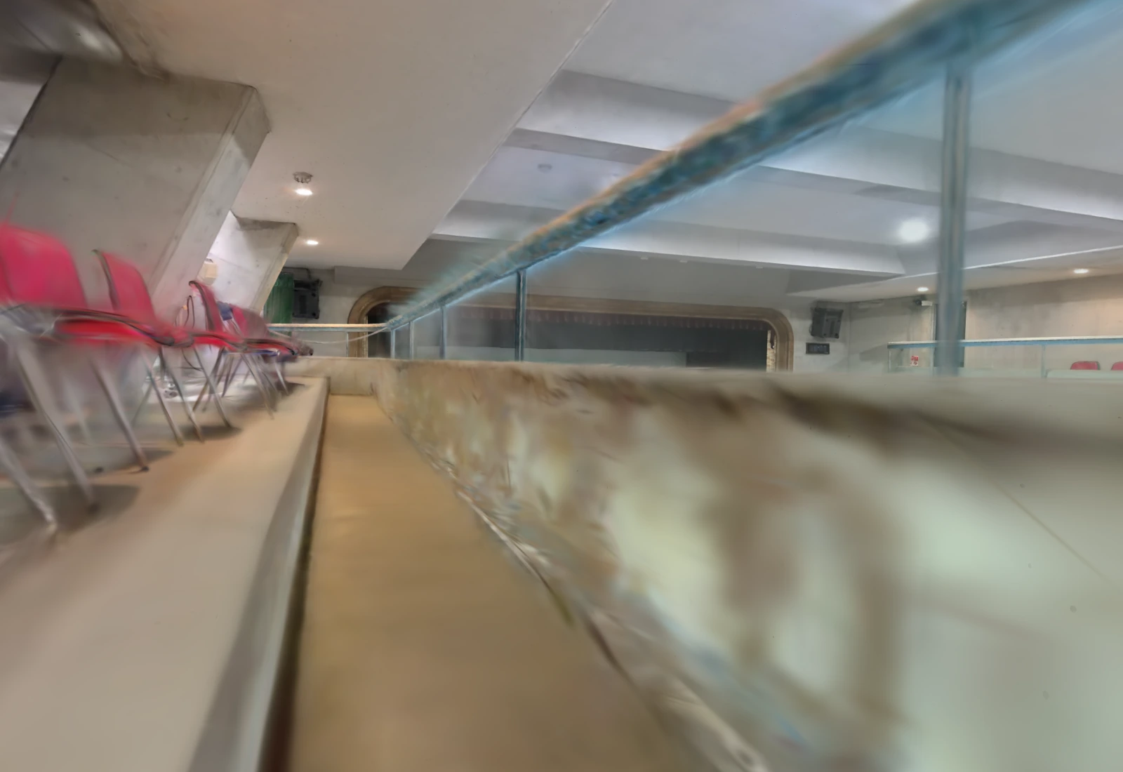
The following images show the current model and original 3DGS from matched cameras.
No overlay or image warp has been applied.
For each location, the model appears first and 3DGS second.
Stage
Rear
Left side
Right side
Ceiling
Upper gallery
08 Current limits and conclusion
Combining 3DGS with captured images makes it possible to build editable geometry while retaining a visual record of the whole space.
Repeated Codex modeling and comparison passes helped refine the ceiling, continuous curved elements and local details such as the stage-front panels.
This model is not yet suitable for commercial use.
Comparison with the original 3DGS still shows large location-dependent differences in wall positions and component sizes.
Hidden areas and component thicknesses include estimates, so the result is not a replacement for measured drawings or a construction model.
The useful pattern is not to ask AI for a finished hall in one pass.
Keep 3DGS as the comparison baseline, divide the scene into areas, build them separately and return to the same cameras after every revision.
At the same time, the MCP-based workflow used here cannot reproduce the hall completely on its own. The current result should be treated as a rough model and finished manually. The important part was recognising that limit and assigning the right resources to reach delivery quality. Professional review, correction and data management are still required after the AI pass.
Faithfully reproducing an existing real-world object is still a difficult task for current AI systems. AI can fill missing information with plausible geometry, but photographs and 3DGS do not reveal every dimension, component thickness or hidden structure. A local correction can also conflict with the global coordinates or neighbouring components elsewhere in the space.
AI is therefore useful for proposing forms, producing a rough model and repeating comparison renders. Faithful reconstruction still requires measured dimensions or drawings as constraints, followed by final adjustment by a professional modeller.
The main-task log increased by approximately 251.74 million tokens: 247.69 million cached input tokens, 3.57 million uncached input tokens and 0.48 million output tokens. At the published API rates this is about US$307, or approximately ¥50,100 using the Bank of Japan's September 2026 reference rate of ¥163 per US dollar. This is an API-equivalent estimate, not the actual Codex app charge, and excludes sub-agent usage and local computer costs.
This work was carried out on the first day of GPT-6 Astra's public availability, while the production method was still being established. Predefining the work areas, locking the comparison cameras and narrowing each revision scope can further reduce elapsed time, token use and the equivalent cost.
Scanning real spaces and building editable 3D models
LOCAHUN 3D can support workflows from 3DGS capture and visual review through editable models for film and simulation.
Contact us →